by Kerry Imming, August 1999
Do you have a rechargeable battery pack that needs to be discharged prior to recharging or storing? If so, you may be interested in this simple, low-cost circuit I created for my use. Depending on how many parts you have available, it can be built for around $20. I've tried my best to make the information provided here as accurate as possible. If you have comments or suggestions, please e-mail them to me at kcimming@pobox.com.
I have an electric radio-controlled boat that uses a 6-cell, 7.2-volt nickel cadmium (NiCad) battery. The instructions for the charger recommend discharging the battery pack before recharging. The problem is that the discharge function built into my charger requires close monitoring of the battery voltage. Discharging below 0.9 volts per cell can damage the battery by causing a voltage reversal on one of the cells. The circuit described here was designed to automatically discharge the battery to the correct voltage.
My goal was to create a device that could simply be connected to the battery to discharge it without any monitoring. It must discharge down to about 5.4 volts (6 cells * 0.9 volts/cell). The circuit must then shut off so the device could remain connected for a period of time (at least over night) without damaging the battery. The circuit described here meets these goals.
The biggest challenge in this circuit was getting a reliable voltage reference from a battery that is discharging from 7.2V down to 5.4V. Keeping component count low was also a concern since I wanted to use point-to-point wiring. Finally, the devices had to draw VERY low current after discharge completion. Maxim Integrated Products supplies a "Micropower Under/Over Voltage Detector" that is ideal for this application.
The figure below shows the schematic diagram for the Nicad Batter Discharger. There are three parts to the circuit.
| IC1 | ICL7665 | Voltage Monitor with Dual Over/Undervoltage Detection | Digi-Key | $4.37 |
| Q1 | IRFZ14 | HEXFET Power MOSFET | Digi-Key | $0.79 |
| R1 | 33K | 1/8 Watt Resistor | ||
| R2 | 100K | 1/8 Watt Resistor | ||
| R3a,b | (40K) | 33K + 6.9K 1/8 Watt Resistors in series | ||
| R4 | 33K | 1/8 Watt Resistor | ||
| R5 | 330 | 1/8 Watt Resister | ||
| R6 | 3.75 Ohm | 40 Watt, four 15 Ohm 10W power resistors in parallel | ||
| R7 | 10K | 1/4 Watt miniature potentiometer | ||
| Fan | Shicoh 0410-N-5E, 5 volt | Jameco | $6.95 | |
| Case | Jameco #151159 or equivalent | Jameco | $4.95 | |
| Conn1 | Std. batter connector with 8" leads | Tower Hobbies | $1.89 | |
| Misc. | T0-220 heatsink, Printed circuit board, wire |
R1, R2, and R3 values are calculated using the ICL7665 datasheet. The configuration used is shown in figure 5 of the datasheet, "Threshold Detector, Vin = V+". For this application, V(U) = 7.2 Volts and V(L) = 5.6 Volts.
R(Load) is calculated as: R6 = (V - V(DS)) / 1.7A = (7.2 - 0.8) / 1.7 = 3.8 Ohm. Note that as the battery voltage discharges down to 5.6 volts the current drops to about 1.3 A.
Layout is not critical, the main goal is to make the wiring job as easy as possible. I used point-to-point wiring. Remember to use 18-20 gauge wire for the part of the circuit from the battery through the load (R6 & Q1) to ground.
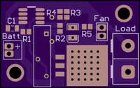
The following figure shows the layout I used. I stacked the power resistors to save circuit board space. Originally I thought I could get the circuit into a very small case and still cool it. I was wrong. I kept the circuit board and layout, but packaged it into the larger case that is listed in the bill of materials.
An optional circuit board layout was created by Doug Gerrard and released as a shared project in the OSH Park community.
OSH Park-Battery Discharge Ckt
To calibrate the Nicad discharger, set potentiometer R7 to the middle of it's range. Connect the circuit to a variable power supply at 7.2 volts. The discharge circuit will now be operating and LED D1 lit. Monitor the voltage while gradually lowering it until the discharger shuts off. This should be somewhere near 5.6 volts. Adjust R7 until the shut-off voltage is 5.6 volts.
Originally I designed this circuit to have less hysteresis, but this resulted in the load oscillating off and on. A nicad battery that is nearly discharged will still produce 7.2 volts (or close) under no-load conditions. This circuit is set to start discharging when the battery is connected and discharge continuously to 5.6 volts.
Proper airflow and cooling is important as this circuit can generate a lot of heat if the battery being discharged still contains a significant level of charge.
Load R6 and the fan could also be replaced with a connector so that an existing battery discharger could be used as the load. I chose not to do this so I could discharge one battery pack while charging another.
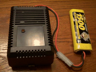
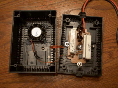
This is a view of the completed nicad discharger. The following inside view shows the layout of the circuit board and the fan connected into the case with hot-melt glue.
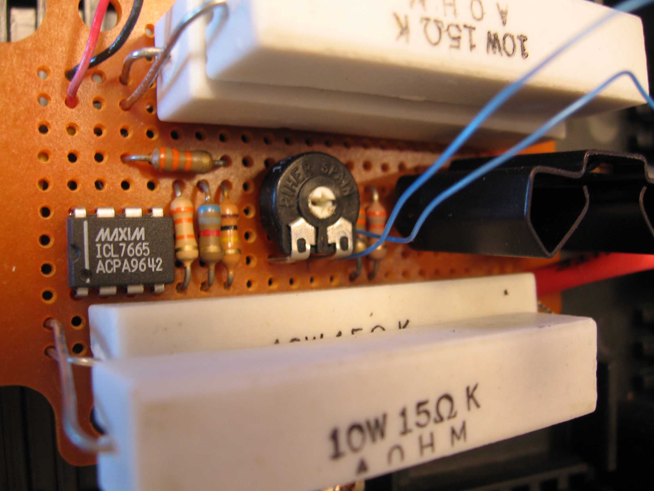
The following pictures show more detailed views of the circuit board.
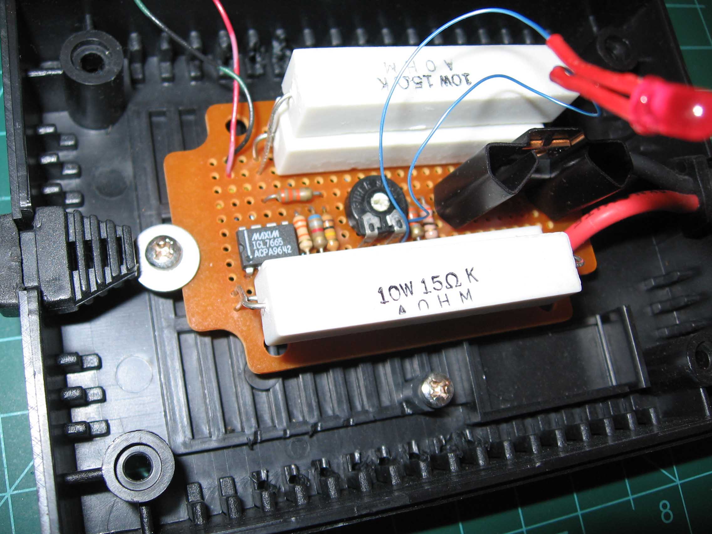
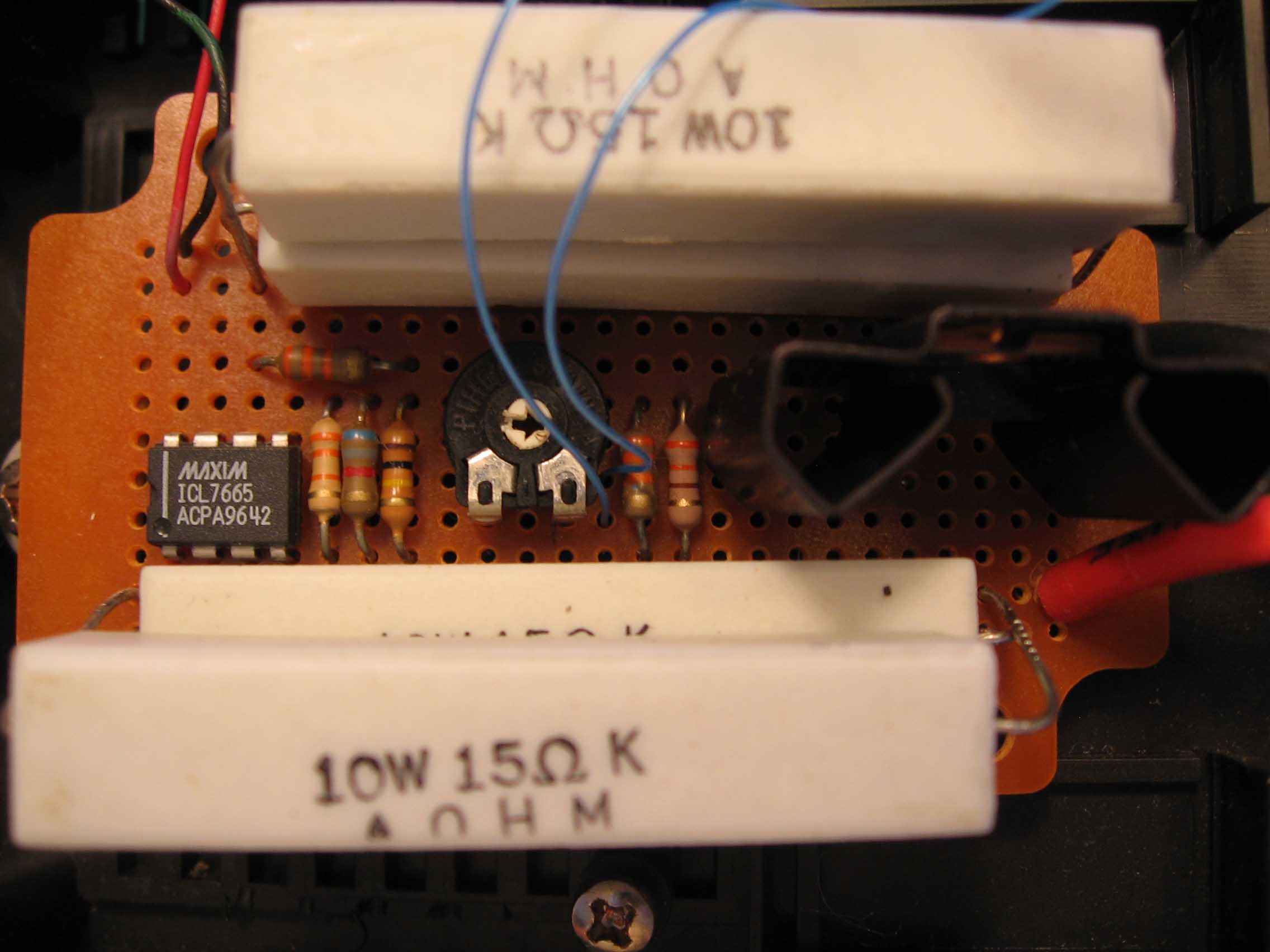
Note in the following pictue how the resistors on either side of the board are really two stacked on top of one another, four total. They were placed apart to help keep them cool.
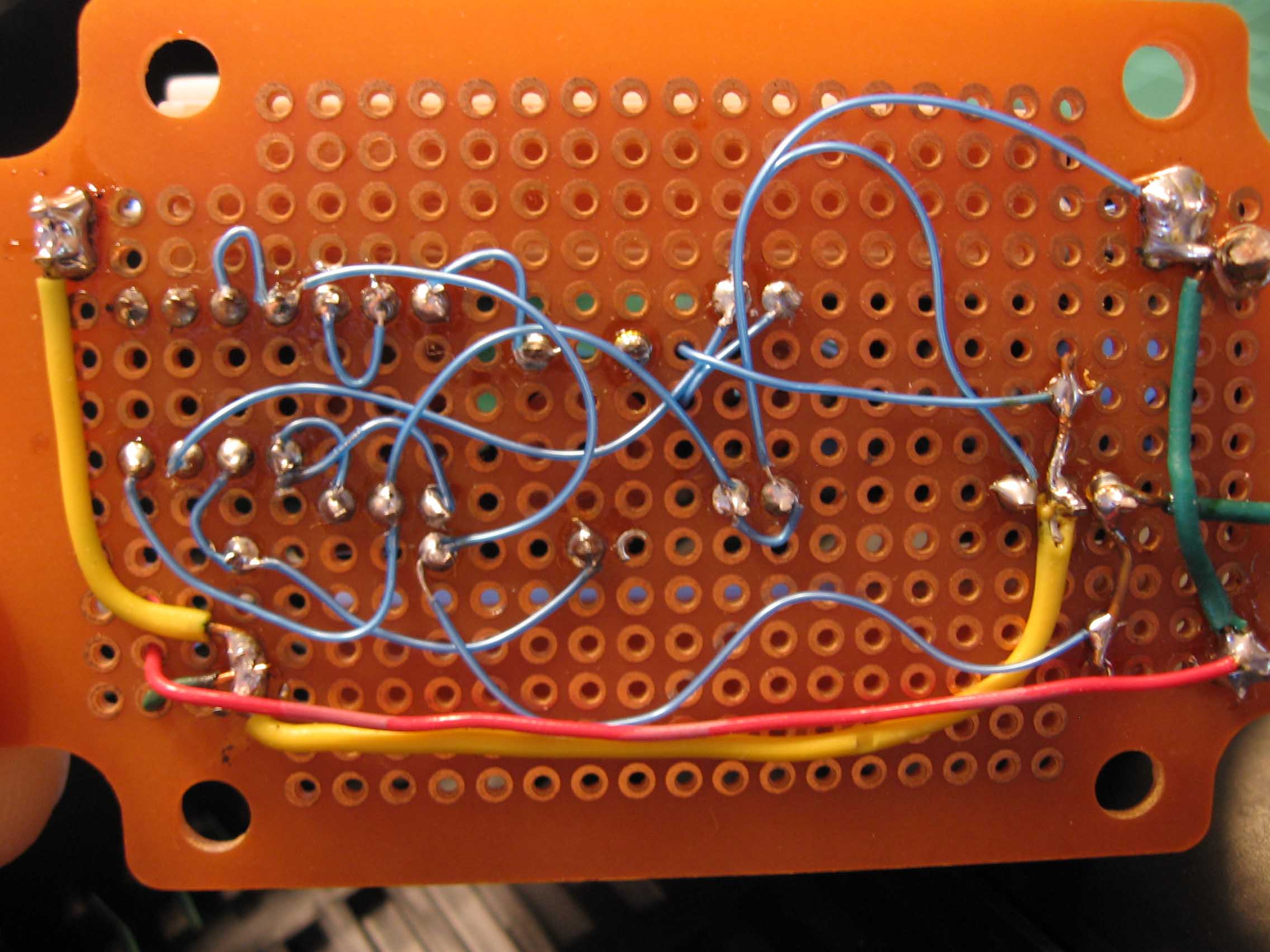
This is a picture of the back side of the circit board to show the point-to-point wiring used.
Maxim Integrated Products
120 San Gabriel Drive
Sunnyvale, CA 94086 USA
Tel: 408-737-7600, 1-800-998-8800
http://www.maxim-ic.com/
International Rectifier
233 Kansas St.
El Segundo, CA 90245 USA
Tel: 310-322-3331
http://www.irf.com/
Updated July 12, 2011 to add detailed pictures of circuit board.
Updated March 11, 2014 to add reference to circuit board.