Kerry Imming
October 18, 2008
Lego NXT VEX Decoder
Overview
The Lego NXT VEX Decoder provides remote control capability to Lego NXT robotics creations using the VEX robotics transmitter and receiver. The decoder is an adapter that connects the VEX receiver to any sensor port on the Lego NXT brick. The decoder is powered from the Lego NXT brick. Lego NXT programs use the VEX Decoder as a sensor and can respond to the position of the transmitter controls.
Description
The Lego NXT VEX Decoder is built using the "Sensor building kit for NXT with PCF8574 IC" as the base. The PCF8574 is replaced with a Microchip PIC 16F690. The PIC implements the I2C slave function as well as the VEX receiver decoding. The six RC channels are converted into 1-byte values (0 – 255) that can be accessed by the NXT.
The remote control provides four analog channels via two joysticks, each with an X and Y axis. There are also two digital channels controlled by momentary switches on the back of the transmitter. The NXT brick can read the values for each of the six channels using the NXT-G I2C block provided with the mindsensors.com "Sensor building kit for NXT with PCF8574 IC". These values can be used to control program actions. For example, two channels can be used to control motor speed and direction to make a remote control vehicle.
Block Diagram
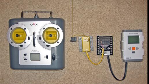
The block diagram below shows how the VEX Decoder connects between the VEX receiver and the Lego NXT brick. The transmitter and receiver are the standard parts provided with the VEX Robotics Systems 6-Channel Transmitter/Receiver add-on kit, available from VEX Robotics Systems, All Electronics Corporation, or E-Bay. The VEX Decoder is the circuit and firmware described in this paper. It is connected to the receiver using the provided RJ-10 cable, one end of which is cut off and hard-wired into the VEX Decoder. The VEX Decoder connects to the Lego NXT brick sensor port using a standard Lego NXT cable.
The following picture shows the real components from the block diagram:
What You Need
- Sensor building kit for NXT with PCF8574 IC and NXT-G I2C block
- PIC16F690
- vex_decoder.HEX (compiled from vex_decoder.c)
- 20-pin DIP socket
- wire and tools to make point-to-point wiring connections
- vex_decode.rbt
- ic2_vex – optional NXT program to display VEX Decoder register value
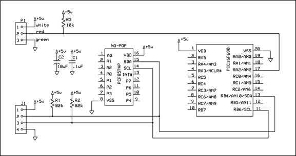
Circuit
The VEX decoder connects to the Lego NXT brick as an I2C slave using a standard Lego NXT cable and the Lego Jack (J1) provided by the Mindsensors sensor building kit. The VEX decoder connects to the VEX receiver via a single-wire connection using the RJ-10 plug (P1). Power is provided by the Lego NXT brick for the PIC microcontroller and the VEX receiver (via J1).
Circuit Board
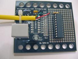
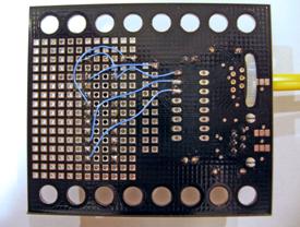
The mindsensor sensor building kit is used as the main circuit board for the VEX Decoder. The PIC16F690 and the 10K pull-up resistor are placed in the board’s prototyping area. The PCF8574 is left off. The VEX receiver cable is cut off and wired to +5V power, ground, and to the 10K pull-up. The yellow wire from the cable is left unconnected. Connections to the prototyping area are made with point-to-point wiring as shown in the following pictures.
Front: Back:
Register Address Map
|
I2C Address |
Value Range |
Type |
Function |
|
0x40 |
90-200 |
Analog |
Channel 1 – Right Joystick left/right |
|
0x42 |
90-200 |
Analog |
Channel 2 – Right Joystick up/down |
|
0x44 |
90-200 |
Analog |
Channel 3 – Left Joystick up/down |
|
0x46 |
90-200 |
Analog |
Channel 4 – Left Joystick left/right |
|
0x48 |
0 or 255 |
Digital |
Channel 5 – Left switch on back |
|
0x4A |
0 or 255 |
Digital |
Channel 6 – Right switch on back |
|
0x4C |
N/A |
|
Reserved |
|
0x4E |
N/A |
Status |
Not Used (I2C Error Status) |
The returned values vary slightly due to the resolution of the delay measurement. The value 145 corresponds to the default (center) joystick position. For up/down channels 90 corresponds to maximum UP and 200 corresponds to maximum DOWN. For left/right channels 90 corresponds to maximum LEFT and 200 corresponds to maximum RIGHT.
NXT Program
The VEX decoder can be accessed using NXT-G programming via the NXT-G I2C block provided with the mindsensors.com sensor building kit.
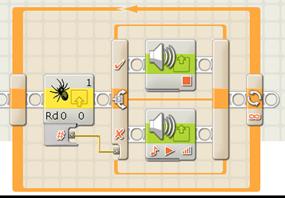
The first example plays a sound when the left-rear transmitter switch is pressed on and stops when the switch is pressed off. The program reads from address 0x48 to get the status of channel 5 (the left-rear transmitter switch). The value is fed into a switch block where it is tested to see if the value is zero. If the value is non-zero a sound is played. If the value is zero the sound is stopped.
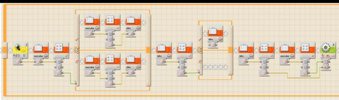
The second example uses an analog joystick channel to control the speed and direction of a motor. The program reads from address 0x42 to get the value of channel 2 (right joystick up/down). The value is stored in variable “newvalue”. Newvalue is compared to 145, the center (default) joystick position. If newvalue is greater than 145, the variable “delta” is set to newvalue-145. Otherwise, delta is set to 145-newvalue. The result is that the variable delta contains the positive offset from the center position.
The next set of NXT-G blocks compare the value of delta with 5 and reset delta to zero if less than 5. This creates a NULL zone around the joystick center where the motor is off. This is optional, but helps prevent the motor from “hunting” for a center position when the receiver values drift slightly, which they tend to do.
The final set of NXT-G blocks multiply delta by 2 to create a range of 0-100 (approximately) for the motor. Newvalue is compared to 145 to create a logic value for the motor direction. Newvalue greater than 145 produces a TRUE logic value for the motor direction, which sets the motor direction to FORWARD.
PIC Firmware
The PIC firmware is written in C using HI-TECH software’s freeware PIC-Lite compiler with the HI-TIDE integrated development environment. After initialization there are two main components to the firmware.
The first code component is the I2C slave interface control. This is handled by the function SSP_Handler called from the PIC interrupt service routine (ISR). The only expected interrupts are from the Synchronous Serial Port (SSP) logic; other interrupts will cause a watch-dog time-out. The handler itself is based roughly on the state machine from Microchip’s Application Note AN734 with adaptations made to support the VEX Decoder’s range of addresses.
The second code component is the VEX receiver decoder loop. This is the main (and only) loop in the run-time code and is based on Jon Williams’ VEX Receiver Decoder algorithm. Instead of generating servo pulses on the PIC port B pins, this code captures the pulse width information into an I2C-readable register for each channel. The first while loop waits for the long (8 to 9 ms) synchronization pulse. The next section is a for loop that handles the analog channels. Note that the channels are numbered 0 to 5 in the code. The last section handles the digital channels. For the digital channels a value of 0 (ISOFF) or 255 (ISON) is stored in the register for the channel depending on whether the channel is OFF or ON respectively.
PIC Port C was used to indicated the state of internal events during code debug. There are still some remnants of that debug code, but they are not used functionally.
Possible Extensions
- Add A0..A3 input to PIC to allow the I2C address to be user-selectable
- Add In-Circuit Serial Programming (ICSP) connector to decoder so PIC firmware can be updated in-place
References
- mindsensors.com, “Sensor building kit for NXT with PCF8574 IC”, www.mindsendors.com , “NXT Accessories”
- Williams, Jon, “VEX Receiver Decoder Circuit/Firmware”, downloaded from http://www.allelectronics.com/mas_assets//spec/JS-6.pdf , October 18, 2008
- Bowling, Stephen and Raj, Naveen, “Using the PIC Devices' SSP and MSSP Modules for Slave I2C Communication”, Microchip Application Note AN734, 1/2/2008.
- Microchip Technology Inc., “PIC16F631/677/685/687/689/690 Datasheet”, 2007.
- Microchip Technology Inc., “PIC16F631/677/685/687/689/690 Rev. A Silicon/Data Sheet Errata”, 2008.
- HI-TECH Software, HI-TECH C PRO for the PIC10/12/16 MCU Family (Lite mode) and HI-TIDE Integrated Development Environment, http://microchip.htsoft.com/downloads/demos.php
- VEX Robostics Systems, “VEX Robotics Transmitter and Receiver Kit”, http://www.vexrobotics.com/vex-robotics-transmitter-receiver-add-on-kit.shtml